


Views: 0 Author: Site Editor Publish Time: 2026-09-30 Origin: Site


The adoption of geometric lighting grids has shifted from a niche aesthetic to an industry standard for high-performance workspaces. Buyers frequently purchase grid systems without assessing their existing ceiling architecture. This oversight leads to compromised structural integrity, uneven illumination, conflicts with existing ceiling hardware, or costly custom mounting modifications. This guide provides a technical framework for evaluating how different ceiling shapes, materials, and structures accommodate hexagonal LED lights. We detail how to ensure optimal light dispersion, safe mounting, and seamless power integration regardless of your specific ceiling type. You will learn exact hardware requirements, load distribution methods, and wiring strategies to execute a professional-grade installation.
Shadowless lighting requires precise overlapping beam angles from multiple light sources. This requirement forms the baseline for automotive inspection and detailing tasks. The shape of your ceiling directly impacts the distance between the light source and the floor. This distance alters both the beam angle spread and the overall light intensity hitting the working surface. A perfectly flat lighting plane ensures uniform lux distribution across the entire room. When a ceiling forces the lighting grid out of a horizontal alignment, the light dispersion becomes uneven. You will experience harsh glare in some areas and deep shadows in others. Maintaining a consistent distance from the floor is non-negotiable for professional workspaces.
To achieve the 750 to 1000 lux required for car detailing lights, you must control the mounting height. The physics of light dictate that intensity drops exponentially as distance increases. This principle heavily influences how you approach different ceiling shapes. If your ceiling architecture forces you to mount the fixtures too high, the working surface lux will drop below acceptable levels. Conversely, mounting them too low creates intense hot spots on reflective surfaces. The ideal ceiling shape allows you to position the lighting grid exactly where the beam angles intersect perfectly at the working height.
A fully assembled geometric lighting grid carries significant cumulative weight. You must account for the polycarbonate housings, aluminum connectors, internal wiring, and power supply units. While individual light tubes feel lightweight, a massive array creates substantial downward force. A standard 5-hex by 12-hex grid can weigh upwards of 50 pounds. Your ceiling must handle this continuous static load without sagging or failing. Relying solely on drywall anchors for a large grid is a severe installation risk. The constant pull of gravity, combined with building vibrations from garage doors or heavy machinery, will eventually loosen standard drywall toggles.
Establishing solid load-bearing anchor points is mandatory. You must locate structural wood joists, steel trusses, or solid concrete to support the primary weight of the system. The shape and material of your ceiling determine how easily you can access these structural supports. Flat ceilings with standard 16-inch or 24-inch joist spacing make load distribution relatively simple. Complex ceiling shapes often hide structural members or place them at irregular intervals. You must plan your mounting strategy around the structural skeleton of the building, not just the visible surface material.
LED fixtures generate heat that must dissipate efficiently to maintain diode lifespan. The space above the fixtures plays a major role in thermal management. Flush mounting against heavily insulated ceilings can trap heat around the polycarbonate housings. You must ensure adequate airflow around the entire grid. Furthermore, the power supply units require specific placement. These transformers convert line voltage to the low voltage required by the LEDs. They generate their own heat and must remain accessible for future maintenance.
Evaluating the ease of routing concealed wiring depends entirely on your ceiling architecture. Hollow cavities above drywall allow for clean, hidden cable runs. Solid ceilings eliminate this possibility entirely. You must balance the aesthetic desire for hidden wires against the physical constraints of the building materials. Electrical compliance requires all connections to happen inside approved junction boxes. Your ceiling shape dictates where these boxes can be legally and safely installed. Surface-mounted solutions become necessary when concealed routing is structurally impossible.
Flat drywall ceilings offer high compatibility for these lighting systems. They represent the ideal scenario for flush-mount installations. The uniform surface allows the grid to sit perfectly flat, maximizing aesthetic appeal. However, successful evaluation requires locating the hidden ceiling joists for secure anchoring. You cannot rely on the drywall alone to support the entire structure. Installers must use magnetic stud finders to map out the wooden or metal framing behind the gypsum board. Once mapped, you align the grid's primary mounting points with these joists.
Toggle bolts can provide secondary support for sections of the grid that fall between joists. The primary load must always rest on structural framing. The main trade-off with flush mounting on drywall is accessibility. Once the grid is secured tightly against the ceiling, accessing the wiring becomes difficult. You must complete all electrical connections and testing before final mounting. This process requires precise initial measurements and careful handling of the assembled grid. Any unevenness in the drywall taping or mudding will cause the rigid connectors to flex, potentially stressing the electrical contacts.
Vaulted and pitched ceilings present moderate compatibility and require secondary hardware for successful installation. You cannot flush-mount these fixtures directly to a sloped surface. The grid must remain perfectly horizontal to function effectively. Following the pitch of the ceiling directs the light at an angle, creating harsh, directional shadows across the room. This defeats the purpose of installing a multi-directional geometric array. To solve this, installers must suspend the entire system from the sloped ceiling.
Implementation requires adjustable aircraft cable suspension kits. You must attach anchor points to the sloped ceiling and drop cables down to the grid. Installers must calculate varying cable lengths to achieve a perfectly level structure. The cables attaching to the higher peak of the vault will be significantly longer than those attaching near the lower walls. This process demands laser levels and meticulous adjustments. The resulting installation looks spectacular, as the grid appears to float horizontally within the vaulted space, delivering perfect downward illumination.
Exposed joists and open truss ceilings offer very high compatibility for geometric lighting. These environments provide maximum flexibility for both flush mounting and suspension. You can mount the grid directly to the bottom chords of the trusses or the faces of the joists. The open nature of the ceiling makes wiring incredibly simple, as cables can run freely along the structural members. This architecture is common in commercial garages, warehouses, and modern industrial-style workspaces.
Implementation challenges arise only when the grid dimensions do not perfectly align with the joist spacing. If the mounting holes on the connectors fall into empty space, you cannot secure the grid. In these cases, a secondary mounting sub-frame becomes necessary. Installers typically use 1-5/8 inch Unistrut or aluminum channels mounted perpendicular to the existing joists. This creates a custom, rigid mounting plane exactly where the grid requires support. The sub-frame adds material cost but guarantees absolute structural integrity and perfect alignment.
Drop ceilings present low to moderate compatibility and always require structural reinforcement. Standard acoustic tiles possess zero load-bearing capacity. They will immediately break under the weight of the fixtures. Furthermore, the existing T-bar metal grid is designed only to hold the lightweight tiles. Attaching a large lighting array directly to the T-bars will cause the metal to warp, twist, and eventually collapse. You must completely bypass the drop ceiling structure to ensure a safe installation for honeycomb LED lights.
Risk mitigation requires anchoring directly to the true structural ceiling hidden above the acoustic tiles. Installers use concrete anchors or joist hangers on the true ceiling, then drop threaded rods or steel suspension cables down through the drop ceiling plane. You must carefully drill small holes through the acoustic tiles to allow the cables to pass through. The lighting grid then hangs from these cables, hovering just below the drop ceiling. This method transfers all weight to the building's primary structure, completely protecting the fragile acoustic grid.
Solid concrete and corrugated metal ceilings offer massive structural integrity but present challenges for aesthetic concealment. These surfaces can easily support the weight of the largest lighting arrays. However, you cannot conceal wiring above the ceiling plane. Every cable, junction box, and transformer must remain visible on the surface. This architectural reality requires careful planning to maintain a clean, professional appearance. You must treat the power delivery system as a visible part of the installation.
Implementation requires specific masonry hardware. You must use concrete anchors, such as 3/16-inch Tapcons, to secure the mounting clips directly into the slab. For corrugated metal roofs, self-tapping screws driven into the structural purlins provide the necessary support. Power delivery requires surface-mounted metal conduit (EMT) to route cables safely to the grid. The conduit protects the wiring from physical damage and ensures compliance with commercial electrical codes. While the wiring remains visible, neatly bent and painted conduit can blend seamlessly into an industrial environment.
| Ceiling Type | Compatibility | Primary Mounting Method | Required Hardware | Wiring Approach |
|---|---|---|---|---|
| Flat Drywall | High | Flush Mount | Wood screws, toggle bolts | Concealed in ceiling cavity |
| Vaulted / Pitched | Moderate | Suspension | Aircraft cables, anchors | Concealed at peak, dropped down |
| Exposed Joists | Very High | Flush or Suspension | Lag bolts, Unistrut | Exposed along structural members |
| Drop Ceiling | Low (Needs Reinforcement) | Suspension (Bypass) | Threaded rods, true-ceiling anchors | Concealed above acoustic tiles |
| Solid Concrete | High (Structural) | Flush Mount | Masonry anchors (Tapcons) | Surface-mounted EMT conduit |
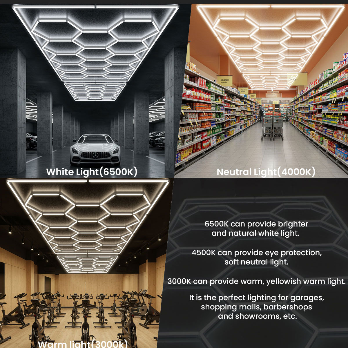
Ceiling height dictates your entire installation strategy due to the physics of light dispersion. Low ceilings, typically under 8 feet, mandate flush mounting. You must maintain adequate physical clearance for vehicles, equipment, and personnel moving beneath the grid. However, mounting powerful fixtures this low introduces the risk of severe glare. The proximity to the floor creates intense hot spots on reflective surfaces like polished concrete or vehicle paint. You must carefully position the grid to minimize direct eye contact with the light source.
High ceilings, exceeding 12 feet, present the opposite problem. Flush mounting a grid at this height results in massive light loss at the working surface. The Inverse Square Law dictates that doubling the distance from the light source reduces the illumination to one-quarter of its original intensity. To maintain adequate lux levels, suspension becomes mandatory. You must use cable systems to bring the grid down to an optimal 9 to 10-foot working height. This approach preserves the light intensity while utilizing the vertical space of the building efficiently.
Most residential garages and commercial detailing bays feature ceiling-mounted obstacles that interrupt a continuous flat plane. Garage door tracks, automatic openers, bulky HVAC ductwork, and low-hanging structural I-beams frequently block the ideal installation path. Attempting to force a standard rectangular grid into a space with these obstructions usually results in compromised lighting placement or physical interference with moving parts. You must plan around these obstacles before assembling the system.
The solution lies in leveraging the modular nature of the lighting system. These grids consist of individual tubes and multi-way connectors. You are not forced to build a perfect rectangle. Grids can be customized into U-shapes, split arrays, or hollow rectangles to bypass garage door openers entirely. You can omit specific sections of a hexagonal light setup to allow clearance for ductwork without sacrificing overall lux levels in the room. This modularity allows you to adapt the lighting design to the specific architectural quirks of your space.
Routing power cables presents distinct challenges depending on the ceiling architecture. On open truss ceilings, hiding cables requires meticulous zip-tying along the top edges of the structural members. The goal is to keep the wires invisible from the floor while maintaining safe routing practices. Finished drywall ceilings allow you to hide the cables completely inside the ceiling cavity, but this requires drilling access holes and fishing wires through insulation and framing.
The placement of LED drivers requires careful consideration. These transformers convert high-voltage building power to the low voltage used by the grid. They must remain accessible for future maintenance or replacement. You cannot permanently seal them behind drywall without an access panel. In open ceilings, drivers are often mounted high up on a wall or tucked behind a structural beam. They must be hidden for aesthetic reasons but readily available for electricians. Proper cable management ensures the installation looks professional and remains electrically safe.
Large grid configurations face a significant risk of structural sagging. When you assemble a massive array, the center of the grid bears tremendous weight. The polycarbonate tubes and aluminum connectors have slight inherent flex. Over a large span, this flex accumulates, causing the center of the grid to bow downward. This sagging ruins the aesthetic appeal and puts severe stress on the electrical connections inside the joints.
You must implement central anchor points to maintain a rigid, planar structure. Regardless of the ceiling shape, you cannot support a large grid only by its perimeter. Installers must map out anchor points evenly across the entire interior area of the grid. If flush mounting, secure the central connectors directly to the ceiling joists. If suspending the grid, drop additional aircraft cables to support the middle sections. Consistent, evenly distributed support is the only way to prevent sagging and ensure long-term structural integrity.
| Grid Configuration | Total Dimensions (Approx.) | Perimeter Anchors Required | Central Anchors Required |
|---|---|---|---|
| 1-Hex by 2-Hex | 4ft x 8ft | 6 to 8 | 0 |
| 2-Hex by 5-Hex | 8ft x 16ft | 12 to 14 | 2 to 3 |
| 3-Hex by 8-Hex | 12ft x 24ft | 18 to 20 | 6 to 8 |
| 5-Hex by 12-Hex | 20ft x 36ft | 26 to 30 | 12 to 15 |
Direct flush mounting provides the cleanest aesthetic and requires the lowest hardware cost. The grid sits tightly against the ceiling, appearing as an integrated architectural feature. This method is best suited for flat drywall ceilings, low-clearance environments, and perfectly aligned exposed joists. The installation process is straightforward, relying on standard screws and anchors provided with most kits.
However, flush mounting has zero tolerance for uneven ceiling surfaces. If your drywall has heavy texturing, bowing joists, or poor taping joints, the grid will not sit flat. Forcing the rigid connectors against an uneven ceiling will cause them to bend and potentially crack. You must verify the flatness of your ceiling with a long straightedge before committing to a flush mount. If the ceiling is wavy, you must shim the mounting clips to create a level plane.
Follow these steps for a secure flush mount installation:
Cable suspension systems offer the ultimate flexibility for complex architecture. They are the best choice for vaulted ceilings, high commercial bays, and bypassing fragile drop ceilings. Suspension allows you to set the grid at the exact height required for optimal light dispersion, completely independent of the actual ceiling height. The floating aesthetic is highly sought after in modern commercial designs.
The primary drawback is the installation difficulty. Suspension requires meticulous measuring, leveling tools, and significant patience. You must install multiple ceiling anchors, drop the cables, attach them to the grid, and then adjust every single cable length until the entire structure is perfectly horizontal. This process is time-consuming and often requires a laser level and at least two installers to execute correctly.
Follow these steps for a precise cable suspension installation:
Custom sub-structures solve the most difficult architectural challenges. When joist spacing is irregular, or you are mounting to corrugated metal roofs or concrete ceilings requiring conduit integration, building a secondary frame is often the only solution. Installers use Unistrut or extruded aluminum to build a rigid skeleton attached to the ceiling. The lighting grid then mounts directly to this perfect, custom-built plane.
This framework guarantees absolute structural integrity and perfect alignment. It provides a solid surface to mount heavy transformers and route EMT conduit neatly. The downside is the added material cost and installation time. Building a Unistrut frame requires cutting metal, installing heavy-duty anchors, and assembling the channel nuts and bolts. However, for industrial environments or highly irregular ceilings, it is the most reliable mounting framework available.
Follow these steps to build a custom Unistrut sub-structure:
A: Yes, but they should not be flush-mounted to the slope. They must be hung using adjustable suspension cables to create a level lighting plane parallel to the floor. Following the pitch of the ceiling will cause uneven light distribution and harsh shadows.
A: No. Standard acoustic tiles and T-bar grids cannot support the weight. The grid must be anchored to the true structural ceiling above the drop ceiling using cables or threaded rods that pass safely through small holes in the acoustic tiles.
A: The optimal height for detailing lights is typically between 9 and 10 feet from the floor. This height maximizes illumination while minimizing glare. If your ceiling is higher, suspension systems should be used to lower the grid to this optimal working height.
A: Because the systems are modular, you can omit specific tubes and connectors to build a custom shape. You can create a U-shape or a split grid that routes around the motor and tracks while maintaining a cohesive look and adequate lighting.
A: Yes, using masonry anchors like Tapcons. However, because you cannot run wiring through solid concrete, you will need to use surface-mounted metal conduit to bring power safely to the grid's connection point.
A: Yes. Uneven surfaces will cause the rigid grid connectors to bend when tightened against the ceiling. This bending leads to structural stress on the polycarbonate tubes and can cause the internal electrical connections to fail.


