


Views: 0 Author: Site Editor Publish Time: 2026-09-16 Origin: Site


The shift in professional automotive care means precision lighting is no longer optional. It is a baseline requirement for high-end paint correction and ceramic coating. Workshop owners often make a costly mistake during facility upgrades. They purchase a premium lighting system without calculating precise spatial requirements. This oversight results in unusable bays, compromised vehicle clearance, or harsh light glare that defeats the entire purpose of the fixture.
Installing overhead lighting structures requires more than simply finding an empty spot on the ceiling. You must account for vehicle dimensions, technician movement, and the physical properties of light diffusion. We will break down a systematic framework for calculating the exact vertical and horizontal clearance required to successfully install and operate an overhead lighting grid in a commercial or high-end residential workshop.
Defining a successful installation requires looking beyond basic aesthetics. A properly mounted lighting system delivers uniform light distribution across every vehicle panel. It eliminates shadow zones on the lower third of the vehicle. It also guarantees safe, unobstructed movement for technicians working with power tools. Achieving these outcomes depends entirely on having the correct ceiling clearance when setting up an LED light tunnel.
Distance dictates light intensity. The proximity of the light source to the vehicle surface directly impacts both lux levels and light uniformity on the clear coat. Proper ceiling clearance maintains the optimal 800 to 1200 lux required for accurate defect spotting. If the fixture sits too close to the vehicle, it creates blinding glare. This proximity also concentrates heat, which can accelerate the flashing time of ceramic coatings prematurely.
Mounting the fixture too far away dilutes the light intensity. The light scatters before reaching the paint, making swirl marks and micro-marring difficult to identify. The inverse square law of light means that doubling the distance from the light source reduces the illumination to one-quarter of its original intensity. You must measure this drop-off accurately.
| Distance from Light Source to Paint | Estimated Lux Level (Standard 120W Tube) | Visual Impact on Paint Correction |
|---|---|---|
| 24 inches (Too Close) | 1500+ Lux | Blinding glare, excessive heat, washes out minor defects. |
| 36 to 48 inches (Optimal) | 800 - 1200 Lux | Perfect clarity, highlights micro-marring, comfortable on eyes. |
| 72+ inches (Too Far) | Under 400 Lux | Shadowing occurs, light scatters, defects become invisible. |
Clearance plays a major role in creating ergonomic transition zones. Technicians constantly move their eyes between the intensely illuminated vehicle surface and the surrounding environment. A well-placed lighting structure creates a smooth visual transition between the detailing bay and the lower ambient lighting of the broader workshop.
Ambient shop lighting typically hovers around 50 to 100 lux. If the primary lighting structure is mounted at the wrong height, the harsh cutoff between the 1000-lux work zone and the 50-lux ambient zone causes severe eye strain. Proper vertical clearance allows the light to feather out naturally at the edges of the bay. This gradient prevents optical fatigue during long polishing sessions.
A static vehicle is only one part of the spatial equation. The tunnel must accommodate dynamic human movement. Technicians use dual-action polishers, extension cords, scaffolding, and rolling stools. A detailer polishing the roof of an SUV needs enough overhead clearance to maneuver a machine without striking the light tubes.
Insufficient vertical space forces technicians into unnatural, hunched postures. This leads to fatigue and increases the risk of accidentally damaging the delicate lighting fixtures with tool handles. You must leave enough room for a technician to stand on a work platform and operate a 5-inch backing plate polisher above the vehicle roofline.
Different vehicles demand different spatial parameters. You must categorize your clearance needs based on the primary vehicle types serviced by your facility. Installing car workshop tunnel lights requires a tailored approach to height management. A one-size-fits-all approach will inevitably fail when a non-standard vehicle enters the bay.
Facilities specializing in sports cars and standard sedans have the most forgiving clearance requirements. The average height of these vehicles ranges from 50 to 60 inches. To achieve optimal illumination, you need a minimum ceiling height of 9.5 to 10 feet. This height allows for a critical 3-foot buffer between the roof of the car and the light fixtures.
This buffer provides enough room for light diffusion while keeping the lux levels concentrated on the horizontal panels. Low-profile sports cars like a Porsche 911 sit even lower, meaning a 9.5-foot ceiling provides excellent overhead clearance for aggressive polishing stages on the roof and hood.
Servicing larger vehicles changes the math entirely. Full-size SUVs, heavy-duty trucks, and lifted vehicles typically measure between 70 and 85 inches in height, with some custom builds exceeding 90 inches. To accommodate these dimensions safely, your facility needs a minimum ceiling height of 12 to 14 feet.
Shops servicing a mixed fleet face a unique challenge. A fixed light height that works for a lifted truck will be too high to effectively illuminate a low-profile sports car. In these environments, adjustable suspension systems become necessary. These systems allow technicians to raise or lower the lighting grid using tensioned aircraft cables to maintain consistent lux levels regardless of the vehicle parked underneath.
| Vehicle Category | Average Vehicle Height | Minimum Recommended Ceiling Height |
|---|---|---|
| Sports Cars & Exotics | 45 - 52 inches | 9.5 feet |
| Standard Sedans | 54 - 60 inches | 10 feet |
| Mid-Size SUVs | 65 - 72 inches | 11 feet |
| Full-Size Trucks & Vans | 75 - 85+ inches | 12 to 14 feet |
Installing overhead lighting above an automotive lift compounds your height requirements significantly. Whether you use a mid-rise scissor lift or a full-height 2-post lift, the maximum extension of the lift must be part of your baseline calculation. Failing to account for the lift's maximum extension will result in the vehicle crushing the lighting structure the first time it is raised.
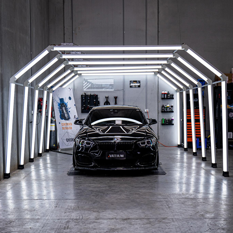
Guesswork leads to expensive modifications. Buyers must use a concrete mathematical framework to evaluate their physical space before purchasing any lighting system. This framework relies on three specific variables that dictate the final installation height.
The lighting system itself consumes vertical space. You must compare the vertical footprint of different mounting styles. Direct-to-ceiling flush mounts are highly efficient, typically consuming only 2 to 4 inches of vertical space. They bolt directly into the drywall or ceiling joists using standard hardware.
Suspended aircraft cable mounts require significantly more room. You generally need 12 to 24 inches of drop space to properly tension the cables and level the grid. Additionally, you must factor in the physical dimensions of the LED tubes. Low-profile tubes measure around 20mm in diameter, while heavy-duty commercial tubes can exceed 50mm. This thickness adds directly to the total vertical footprint of the installation.
The true ceiling height is often irrelevant. You must measure from the floor to the lowest hanging obstacle in the bay. Retrofitted workshops are full of structural and mechanical elements that intrude on usable vertical space. Always map the ceiling topography before ordering.
The working gap is the empty space between the bottom of the LED grid and the top surface of the vehicle. The optimal distance is 3 to 4 feet. This specific gap allows the light to cross-illuminate. If the gap is too small, you will experience severe light banding.
Light banding occurs when distinct, harsh lines of light reflect on the paint, making it impossible to see the true condition of the clear coat between the reflections. The 3-to-4-foot gap ensures the light blends evenly while providing ample room for technicians to wield rotary polishers safely without striking the overhead diodes.
Vertical clearance is only half the equation. Horizontal space dictates the effectiveness of the side-illumination panels and determines whether technicians can actually move around the vehicle. A perfectly leveled ceiling grid is useless if the side walls are too tight to allow proper door operation.
A standard detailing light tunnel requires significant floor width to function properly. The standard width requirement for a professional bay is 13 to 15 feet. This width allows the vehicle doors to open fully without striking the lighting frame or the adjacent walls.
Technicians need at least 3 feet of walking space on either side of the vehicle to operate comfortably. Constricted horizontal space forces detailers to press against the walls, restricting their arm movement and reducing the quality of the polishing work. If a bay is narrower than 12 feet, a full wrap-around tunnel is not viable.
| Bay Component | Minimum Horizontal Space Required | Purpose |
|---|---|---|
| Vehicle Footprint | 7 to 8 feet wide | Accommodates standard and wide-body vehicles. |
| Technician Walkway (Per Side) | 3 feet (36 inches) | Allows safe operation of polishers and rolling carts. |
| Door Swing Clearance | 2 to 3 feet | Prevents door edge damage against walls or light frames. |
| Total Bay Width | 13 to 15 feet | Ensures full operational efficiency and light diffusion. |
Installing a lighting structure too close to existing walls creates severe operational trade-offs. Side-mounted LEDs need distance to diffuse properly. They require at least 3 feet of distance from the vehicle's side panels. If mounted closer, the light becomes overly concentrated, creating hot spots on the doors and fenders.
The angle of these side panels is equally important. Side-illumination panels must be adjusted at a 25 to 45-degree angle. This specific tilt directs the light downward toward the rocker panels and lower doors. If the side lights are mounted perfectly flat against a wall, they shoot light directly into the technician's eyes, causing temporary blindness and severe glare. The 25 to 45-degree angle ensures the light hits the paint, not the operator.
Large-scale lighting structures introduce physical realities that go beyond simple spatial measurements. You must evaluate the structural integrity of your building and plan for complex electrical routing before drilling a single hole.
Commercial-grade aluminum lighting grids are heavy. Depending on the size and configuration, these systems often weigh between 50 and 150+ lbs. Standard 1/2-inch drywall ceilings cannot support this weight independently. You must locate the structural ceiling joists to anchor the system securely.
If joists do not align with your desired bay placement, you have two mitigation strategies. You can span the joists with heavy-duty strut channels (like Unistrut) to create new mounting points, or you can build a secondary freestanding support frame. Relying solely on plastic drywall anchors for a suspended 100-lb lighting grid poses a massive safety hazard to both technicians and vehicles.
A clean installation requires hidden wiring. You must account for the electrical clearance needed above the ceiling or along the upper walls to hide transformers, LED drivers, and heavy-duty wiring harnesses. These components require proper ventilation to prevent overheating.
Do not stuff high-output power supplies into tightly packed, unventilated ceiling cavities. Always consult local commercial electrical codes regarding suspended lighting. Many municipalities require specific conduit routing and dedicated circuits for continuous-load commercial lighting systems. Low-voltage wiring runs must be calculated carefully to prevent voltage drop across large grids.
Once you have calculated your exact vertical and horizontal clearance, you can select a product that fits your physical constraints. Let your tape measure dictate your purchasing decision when selecting a car detailing light tunnel.
Buyers must choose between modular and fixed systems based on their spatial flexibility. Modular hexagonal or grid systems offer immense adaptability. If your ceiling clearance is tighter than expected, or if an HVAC duct is in the way, you can simply omit a section of the grid. You can scale the design down to fit the exact footprint available.
Conversely, rigid, single-piece arched kits require absolute spatial compliance. They cannot be modified on-site. If a fixed arch requires 11 feet of clearance and you only have 10.5 feet, the system will not fit. You must verify the exact outer dimensions of fixed systems before ordering.
Your ceiling height dictates your mounting hardware. For ceilings under 10 feet, direct flush mounts are mandatory. They preserve every inch of available vertical space by bolting the aluminum channels directly to the ceiling surface.
For ceilings over 12 feet, suspension cables are the superior choice. High ceilings pull the light source too far away from the vehicle, causing severe lux degradation. Suspension cables allow you to drop the lighting grid down to the optimal 9.5 to 10-foot working height, bringing the light source closer to the paint while maintaining a level, professional appearance.
A: The absolute minimum ceiling height is 9.5 feet for standard cars and 12 feet for trucks or SUVs. This accommodates the height of the vehicle, the thickness of the lighting fixture, and a mandatory 3-foot working gap between the light and the car's roof for optimal light diffusion.
A: Yes, but standard 8-foot residential ceilings present challenges. Full arched tunnels will not fit. Instead, you must use low-profile, flush-mounted hexagonal grids. These systems mount directly to the drywall, saving vertical space, though you will be limited to detailing standard-height sedans and sports cars.
A: The optimal distance is 36 to 48 inches from the vehicle surface. This specific range allows the light to blend properly, eliminating harsh banding while delivering the 800+ lux necessary for paint correction visibility without causing excessive glare.
A: Side fixtures should be angled between 25 and 45 degrees downward. This positioning provides optimal illumination for lower door panels and rocker panels while preventing the light from shining directly into the technician's eyes, which causes severe glare and fatigue.
A: Yes, large suspended grids can sway in high-airflow commercial environments. To prevent this, installers must use rigid mounting brackets or heavily tensioned aircraft cables. Cross-bracing the suspension wires also eliminates lateral movement caused by industrial fans or open bay doors.
A: It depends on the mounting hardware. Static flush mounts attached directly to the ceiling cannot be adjusted. However, systems installed with adjustable cable-suspension hardware can be raised or lowered to accommodate varying vehicle heights and maintain consistent lux levels.


