


Views: 0 Author: Site Editor Publish Time: 2026-09-28 Origin: Site


A visually striking detailing bay acts as a powerful marketing asset. However, lighting that fails to expose paint defects renders the workspace functionally useless. Improperly positioned lighting creates blinding glare, casts harsh shadows on lower vehicle panels, and washes out the visibility of micro-marring and orange peel. Many shop owners install a hexagonal light grid purely for aesthetics, neglecting the geometric requirements of a professional workspace.
Establishing a technical framework for positioning your lighting grid ensures the setup delivers both visual appeal and uncompromising functional performance. You must base this framework on bay dimensions, ceiling height, lux targets, and detailing workflows. Precision in placement dictates how well you can see high-spots in ceramic coatings, holograms from rotary polishers, and the true condition of a vehicle's clear coat. We will break down exactly where and how to mount these systems to maximize your paint correction efficiency.
Detailing bay lighting serves a strict dual purpose. It must provide a uniform, shadow-free environment for general work like interior cleaning, washing, and coating application. Simultaneously, it must create specific reflection points to evaluate paint condition. Achieving both requires a deliberate approach to fixture positioning. If you mount a grid too high, the light dissipates before reaching the lower panels. If you mount it too low, it creates intense hot spots on the vehicle roof and causes severe eye strain for the technician working underneath it.
Contrast the continuous geometric spread of honeycomb LED lights against traditional isolated linear shop lights. Standard linear tubes create harsh, distinct lines of light separated by dark zones. This uneven distribution forces detailers to constantly move the vehicle or their inspection lamps to see the paint clearly. The interconnected layout of a geometric grid eliminates these dark zones. It provides superior brightness consistency across the entire vehicle surface. The hood, roof, and trunk receive identical illumination levels simultaneously, allowing you to work around the vehicle without constantly adjusting your primary light source.
Address the common misconception that a bright room equals a good detailing room. Over-illumination without directional control washes out the paint surface. When too much ambient light floods a clear coat, it hides fine wash scratches and buffer trails. The geometric design naturally diffuses light to reduce harsh shadows, making them ideal for base illumination. However, this ambient wash depends heavily on correct spatial positioning relative to the vehicle. You want to prevent the light from overpowering the subtle visual cues of paint imperfections. When leveling a ceramic coating, the straight lines of the grid reflect off the wet surface. If you miss a spot during your wipe-down, the reflection of the light tube will look wavy or smeared instead of perfectly sharp. This visual feedback only works if the lights are positioned at the correct angle relative to your line of sight.
For facilities with standard ceilings measuring between 8 and 10 feet, the 8–12 inch drop rule is the industry standard. Suspending the fixture plane slightly below the exposed ceiling or joists serves two primary functions. First, it allows for proper light diffusion. This prevents the light from bouncing directly off the ceiling paint and creating unwanted ambient glare. Second, leaving a gap between the fixture and the ceiling allows for heat dissipation. LED drivers generate thermal energy. Flush-mounting these systems against drywall traps heat, which can prematurely degrade the electronic components and cause localized hot spots on the ceiling.
High ceilings exceeding 12 feet require a different mechanical approach. Flush-mounting a grid at 14 feet renders the light output virtually useless for intricate paint correction at the floor level. In these environments, evaluate cable suspension systems. You must drop the grid to an optimal height—typically 9 to 10 feet from the floor. This specific elevation maintains the required lux levels on the vehicle's roof and hood while keeping the fixtures entirely out of the technician's physical workspace.
Calculating the exact distance from the light source to the vehicle requires measuring the average roofline of the vehicles you service. Follow this framework to determine your exact suspension cable length:
Positioning the grid exactly 3.5 to 4 feet above the highest anticipated roofline ensures consistent brightness without causing technician eye fatigue. If the grid is closer than 3 feet to the vehicle roof, the intensity of the reflection can cause temporary blindness when the detailer looks across the paint plane to check for dual-action polisher haze.
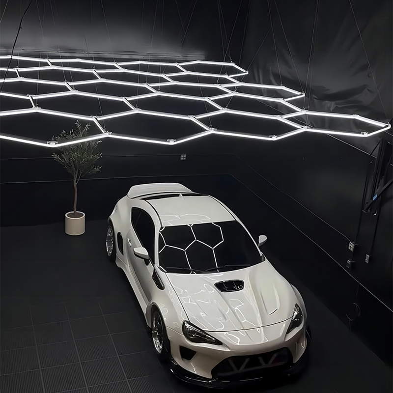
Mapping the grid to your specific vehicle dimensions dictates the overall size of the system you need to order. A common error is sizing the grid exactly to the dimensions of the car. The outer perimeter of the light setup should ideally extend 1 to 2 feet beyond the footprint of the largest vehicle serviced. For example, if you regularly work on large trucks measuring 20 feet long and 7 feet wide, your grid should measure at least 22 feet by 9 feet. This overhang allows the light to cast downward at an angle, illuminating the side panels, doors, and fenders effectively.
| Primary Vehicle Type Serviced | Average Vehicle Footprint (L x W) | Recommended Minimum Grid Size | Ideal Bay Width Required |
|---|---|---|---|
| Sports Cars / Compact Sedans | 15 ft x 6 ft | 17 ft x 8 ft | 12 to 14 Feet |
| Mid-Size SUVs / Large Sedans | 17 ft x 6.5 ft | 19 ft x 8.5 ft | 14 to 16 Feet |
| Full-Size Trucks / Large SUVs | 20 ft x 7 ft | 22 ft x 9 ft | 16 to 18 Feet |
| Commercial Vans / Fleet Vehicles | 22 ft x 7.5 ft | 24 ft x 9.5 ft | 18+ Feet |
Wall clearance and walkway illumination require careful spatial planning. Establish strict guidelines for leaving adequate space between the edge of the grid and the bay walls. If you push the grid flush against a high-gloss painted wall, the light will bounce directly back into the technician's eyes. This destroys their night vision and contrast sensitivity when looking for fine sanding marks. Maintain a minimum clearance of 2 to 3 feet between the outer edge of the lighting matrix and any vertical structural walls.
Multi-bay configurations introduce complex optical challenges. When running continuous or multiple grids across a multi-car detailing studio, spacing requirements become critical. You must avoid overlapping light zones that create confusing multi-directional shadows. If two grids sit too closely together, a technician working on the right side of Bay 1 will cast a shadow from the lights in Bay 2 onto their own workpiece. Separate distinct working bays with at least 4 to 6 feet of unlit ceiling space. This ensures the light remains localized to the specific vehicle being corrected.
Analyze the standard ceiling mount setup. While excellent for horizontal surfaces like hoods, roofs, and trunks, ceiling-only configurations suffer from a steep drop-off in light intensity on vertical surfaces. Gravity dictates that light travels in straight lines. As it passes the beltline of the vehicle, the lower doors, rocker panels, and bumpers fall into shadow. Relying strictly on overhead lighting forces detailers to work blind on the lower third of the vehicle. This increases the risk of burning through clear coat on plastic bumpers or leaving behind high spots during ceramic coating leveling.
Evaluate the integration of wall-mounted grids to solve this vertical illumination deficit. The wrap-around approach involves positioning wall grids at a 45-degree angle or mounting them vertically starting at knee-height. This setup blasts light directly onto the lower panels during polishing and paint protection film (PPF) application. When a technician sits on a detailing stool to polish a rocker panel, the wall-mounted grid provides the exact same ambient clarity that the ceiling grid provides for the hood.
Managing glare and defect visibility on vertical panels requires an understanding of the physics of light reflection. The angle of incidence equals the angle of reflection. Position wall lights so the reflection bounces away from the technician's standard line of sight. If you mount a wall grid exactly at eye level, the reflection off the clear coat will cause temporary blindness. Mount the vertical grids slightly lower, angling the light upward. This reveals texture issues like orange peel on high-gloss finishes without overwhelming the detailer's retinas. You can easily spot sanding pigtails and rotary trails when the light rakes across the panel from a lower angle.
No geometric grid can replace a dedicated point-source inspection light. Hex grids provide a brilliant ambient wash. Point sources provide precise defect exposure. Ambient light fills in scratches, making them harder to see. Directional light hits the edges of a scratch, casting a microscopic shadow that makes the defect visible to the human eye. You must utilize car detailing lights to inspect your compounding and polishing work accurately. Relying solely on a grid will result in a car that looks flawless in the shop but shows heavy swirl marks the moment it pulls out into direct sunlight.
Evaluate newer hybrid grid systems that solve this integration challenge. Advanced setups now feature integrated directional spotlights built directly into the geometric matrix. These systems offer a streamlined, all-in-one solution for both ambient wash and defect spotting. By embedding the spotlights within the grid nodes, you eliminate the need for separate track lighting systems. This keeps the ceiling clean, reduces overall installation complexity, and ensures the directional light originates from the exact same plane as the ambient light.
If you are not using a hybrid system, you need a layout strategy for integrating track lighting or wall-mounted directional fixtures alongside a standard grid. Mount directional track heads on the outside perimeter of the hex grid, pointing inward at a 45-degree angle. This allows the point-source light to cut through the ambient wash of the grid, highlighting holograms and swirl marks. Position these track lights on separate switches so you can turn off the main grid and inspect the paint using only the directional beams.
The Kelvin rating of your grid must match your inspection lights. If your ceiling grid outputs a cool 6500K blue-white light, but your inspection lamps output a warm 4000K yellow light, you will experience severe color-rendering distortion during paint correction. This mismatch makes it impossible to accurately judge paint matching, metallic flake pop, and coating clarity. Standardize your entire bay at a crisp 5000K to 6000K daylight temperature. This ensures what you see in the bay perfectly matches what the customer sees outside.
Break down the recommended lux levels for a professional detailing bay. Lux measures the intensity of light as perceived by the human eye at a specific distance. For general work, washing, and interior detailing, a target of 750 to 1000 lux at floor level is optimal. For intensive paint correction and inspection zones, you need localized intensity exceeding 2000 lux. Grid positioning directly impacts these measurements. Raising a grid by just two feet can reduce the floor-level lux by up to 30 percent due to the inverse-square law of light dissipation.
| Ceiling Height | Recommended Suspension Drop | Target Floor Lux (Ambient) | Primary Detailing Application |
|---|---|---|---|
| 8 - 10 Feet | 8 - 12 Inches | 800 - 1000 Lux | General washing, interior, coating leveling |
| 10 - 12 Feet | 18 - 24 Inches | 750 - 900 Lux | Paint correction, polishing, PPF installation |
| 12+ Feet | Cable drop to 9-10 ft from floor | 800 - 1000 Lux | Heavy defect removal, commercial fleet work |
| Wall Mount (Vertical) | Start 2 feet from floor | 1500+ Lux (on panel) | Rocker panel polishing, lower door inspection |
Evaluate the electrical realities of large-scale illumination. A massive grid draws significant amperage. You must calculate the total wattage of the system and convert it to amps using Ohm's law (Watts divided by Volts equals Amps). If a large grid consumes 1200 watts on a standard 120-volt circuit, it pulls 10 amps. A standard 15-amp breaker should only be loaded to 80 percent of its capacity for continuous loads, which equals 12 amps. Therefore, a single large grid nearly maxes out a standard circuit.
You absolutely need dedicated circuits. Plugging a massive grid into an existing garage circuit that also runs polishers, air compressors, and vacuums will result in constant breaker trips. Consult with a licensed electrician to run dedicated 15-amp or 20-amp circuits specifically for the overhead lighting. Ensure the wiring gauge matches the breaker size—typically 14-gauge wire for 15-amp circuits and 12-gauge wire for 20-amp circuits.
Assess the value of installing dimmable drivers. The ability to control the intensity of the hexagonal LED lights during different stages of the detailing process is a massive operational advantage. When performing heavy compounding, you may want the grid at 100 percent capacity. However, when doing final inspections, dimming the ambient light to 30 percent allows your directional inspection lights to pop. This makes it much easier to spot remaining micro-marring without the grid washing out the surface.
Contrast consumer-grade DIY kits with commercial systems. The market is flooded with cheap, snap-together grids that look good in photographs but fail in professional environments. Commercial systems feature rigid aluminum housings, high-quality polycarbonate diffusers, and robust locking connectors. DIY kits often use brittle plastic connectors that crack under the weight of the assembly and thin acrylic covers that yellow after six months of UV exposure. Professional installation is highly recommended for hardwired, high-amperage setups to ensure long-term reliability.
Address the structural integrity of the grid assembly. A large grid is heavy. Over time, gravity will cause the center to sag if not properly supported. Use rigid aluminum framing if suspending the grid via cables. Ensure adequate anchor points are drilled directly into ceiling joists using lag screws, not just drywall anchors. Drywall anchors will eventually pull out due to the vibration of garage doors and the sheer weight of the fixture. A sagging grid not only looks unprofessional, but it also alters the angle of light hitting the vehicle, creating inconsistent reflection points.
Highlight the critical importance of wiring compliance and fire safety. Always use fixtures that are UL-listed or CE-certified. Detailing bays are wet environments. Moisture and electricity are a dangerous combination. Never hide non-compliant transformers or exposed wiring in ceiling cavities. All connections must be housed in proper junction boxes. The system must be grounded to prevent electrical shock hazards when washing vehicles directly beneath the fixtures.
Position the grid in a way that allows for easy maintenance accessibility. LED tubes and drivers eventually fail. If your grid is mounted flush against a drywall ceiling with no access panels, replacing a single burnt-out tube might require disassembling the entire structural matrix. Suspending the grid with cables or leaving a 12-inch drop allows technicians to easily reach over the top of the grid to unclip connectors and swap out faulty components in minutes.
A: For standard 8 to 10-foot ceilings, mount the grid 8 to 12 inches below the ceiling. This gap allows for proper heat dissipation from the LED drivers and prevents harsh light from bouncing directly off the ceiling paint, which can cause unwanted glare.
A: They provide excellent ambient light that reveals larger defects like orange peel and dents, but they can wash out fine swirls. You must pair them with directional point-source inspection lights to accurately spot micro-marring and fine scratches during paint correction.
A: Yes, advanced hybrid systems feature integrated directional spotlights built directly into the geometric nodes. This provides an all-in-one solution, offering both the ambient wash of the grid and the defect-spotting power of directional lights without needing separate track lighting.
A: Yes, wall mounting is highly recommended. Positioning grids vertically or at a 45-degree angle illuminates the lower doors, rocker panels, and bumpers. This wrap-around approach eliminates the shadows caused by overhead-only lighting, ensuring accurate polishing on lower panels.
A: A professional bay should target 750 to 1000 lux at floor level for general washing and interior work. For intensive paint correction and ceramic coating application, localized inspection zones should reach 1500 to 2000+ lux to ensure total clarity.
A: The outer perimeter of the grid should extend 1 to 2 feet beyond the footprint of the largest vehicle you service. This overhang allows the light to cast downward at an angle, properly illuminating the vertical side panels and fenders.


