


Views: 0 Author: Site Editor Publish Time: 2026-09-02 Origin: Site


The aesthetic and functional appeal of a geometric lighting grid is immediately compromised by flickering tubes, blown breakers, or visible, disorganized wiring. Buyers frequently purchase large lighting grids without evaluating their existing garage electrical infrastructure. This oversight leads to overloaded circuits, severe voltage drops, and potential fire hazards. Proper electrical planning forms the foundation of any successful lighting upgrade. This guide breaks down the technical requirements for powering a hexagonal lighting system. We cover calculating amperage loads, managing LED drivers, and choosing between plug-and-play and hardwired configurations. You will learn how to ensure a safe, professional-grade installation that meets local codes and delivers consistent illumination across your entire workspace.
A successful installation requires uninterrupted power delivery across the entire ceiling. Consistent lumen output across all tubes is mandatory for a professional finish. Strict adherence to local electrical codes ensures long-term safety and performance. You cannot simply plug a massive lighting array into a shared wall outlet and expect flawless results. The infrastructure must match the electrical demand of the fixtures.
Improper power routing in a large grid causes the tubes furthest from the power source to dim. This phenomenon is known as voltage drop. It ruins the seamless look of any hexagonal light pattern. When power travels through multiple connectors and long runs of LED tubes, electrical resistance increases. This resistance reduces the voltage available to the final tubes in the sequence. Strategic power injection points are required to combat this issue. We often see DIY installers daisy-chain 40 tubes together. The first ten tubes burn bright, while the last ten barely glow.
Overloading standard garage wiring with high-output car detailing lights running for extended periods poses significant risks. These systems generate heat at connection nodes. If the amperage draw exceeds the rating of the wiring or the connectors, the plastic components can melt. This creates an immediate fire hazard. Proper thermal management starts with a correctly sized electrical circuit. Using 14 AWG wire on a 20-amp breaker, for example, is a severe code violation that leads to overheating. You must match the wire gauge to the breaker size. 14 AWG pairs with 15-amp breakers. 12 AWG pairs with 20-amp breakers.
Determining total system wattage is your first step. You must calculate the exact power consumption before pulling wire. The formula is straightforward. Multiply the wattage per tube by the total number of tubes in your layout. You must include the power consumption for the outer border lights in addition to the inner grid. A typical setup might include 60 inner tubes and 24 border tubes. Every single tube adds to the total load. If each tube draws 8 watts, 84 tubes draw 672 watts.
Converting that total wattage to amperage tells you what size circuit breaker you need. Divide your total system wattage by your operational voltage. For North American residential garages, this is typically 120V. If your total wattage is 1,200W, dividing by 120V yields a 10-amp draw. This calculation dictates whether you can use an existing circuit or must install a new one.
Running a 240V circuit halves the amperage draw compared to a 120V circuit. This provides a massive advantage for large installations. It allows commercial-scale grids to operate safely on a single breaker without overloading the system. If your lighting kit supports dual voltage, utilizing 240V is highly recommended for wall-to-wall layouts. It reduces heat generation in the wiring and allows for longer continuous runs.
You must apply the 80% rule for continuous loads on circuit breakers. Electrical codes mandate that a breaker should only carry 80% of its maximum rating for loads operating longer than three hours. A standard 15-amp breaker should only support 12 amps of continuous load. This equals approximately 1,440 watts at 120V. You must also identify existing garage appliances on that circuit. Refrigerators, door openers, and air compressors heavily impact the available amperage for your new honeycomb LED lights.
| Common Garage Device | Estimated Wattage | Estimated Amperage (120V) |
|---|---|---|
| Garage Door Opener (1/2 HP) | 500 - 750 Watts | 4.1 - 6.2 Amps |
| Standard Refrigerator | 400 - 800 Watts | 3.3 - 6.6 Amps |
| Air Compressor (Small) | 1,000 - 1,500 Watts | 8.3 - 12.5 Amps |
| Shop Vacuum | 1,200 - 1,440 Watts | 10.0 - 12.0 Amps |
| Space Heater | 1,500 Watts | 12.5 Amps |
| Circuit Breaker Size | Voltage | Max Continuous Amperage (80% Rule) | Max Continuous Wattage |
|---|---|---|---|
| 15 Amp | 120V | 12 Amps | 1,440 Watts |
| 20 Amp | 120V | 16 Amps | 1,920 Watts |
| 15 Amp | 240V | 12 Amps | 2,880 Watts |
| 20 Amp | 240V | 16 Amps | 3,840 Watts |
Many modern kits feature built-in internal drivers. This means 120V or 240V alternating current is routed directly to the starting Y-connector on the ceiling. The conversion to direct current happens inside the individual tubes or connectors. This configuration makes the physical layout easier to wire. However, it requires careful management of high-voltage lines directly at the ceiling level. You must ensure all connections are perfectly seated to prevent arcing. When working with internal drivers, the primary concern is securing the Romex or MC cable safely to the ceiling junction box before transitioning to the proprietary lighting connectors.
Other systems use centralized external transformers. These units step down the high voltage to a safer, lower DC voltage before it reaches the lighting grid. This layout requires planning a hidden, ventilated location to house the bulky transformer. Attic spaces or wall-mounted utility boxes are common solutions. Proper ventilation is mandatory to prevent the transformer from overheating and failing prematurely. If you mount a 1000W transformer in a sealed drywall box, it will overheat within hours. We recommend using louvered access panels to allow passive airflow around external power supplies.
When a driver fails, the symptoms differ based on the configuration. Internal driver failures usually isolate to a single tube or a small cluster of tubes. You simply swap the defective tube. External transformer failures take down the entire grid or a massive section of it. You must test the output terminals with a multimeter to confirm the transformer is delivering the correct DC voltage.
Plug-and-play installations utilize standard garage wall outlets. This is the best use case for small to medium setups. A 5-grid to 14-grid layout typically falls within the safe wattage limits of a standard outlet. This method requires no specialized electrical knowledge. Rapid deployment is the primary benefit. You can assemble and power the grid in a single afternoon. It is also easy to relocate if you move to a new home.
However, this approach has distinct drawbacks. It is aesthetically unpleasing if power cords are visible running down the wall. You are strictly limited by the existing circuit's shared load. If a garage refrigerator kicks on, it might trip the breaker. You also rely on standard 2-prong or 3-prong plug limits, which restrict the total number of tubes you can connect. Extension cords are not a permanent wiring solution. Building codes prohibit running flexible extension cords through walls or ceilings. If you use a plug-and-play kit, the cord must remain visible and accessible.
Dedicated hardwired circuits are mandatory for full-ceiling, wall-to-wall installations. Professional detailing bays demand this level of infrastructure. Hardwiring eliminates shared-load tripping risks entirely. The lighting system operates independently from your power tools and appliances. It allows for completely concealed wiring behind drywall or above drop ceilings. This method easily supports multiple power injection points for massive grids.
The main disadvantage is the requirement for a licensed electrician. Working inside a main breaker panel carries severe safety risks. This results in a higher upfront installation cost. Hardwiring also makes the lighting system a permanent fixture of the building. You cannot easily take it with you if you relocate.
When hardwiring, you must follow a strict sequence of operations. First, map the ceiling joists to determine junction box locations. Second, pull the NM-B cable from the breaker panel to the switch box. Third, run the switch leg up to the ceiling junction boxes. Finally, terminate the wires into the manufacturer's supplied pigtails using Wago connectors or traditional wire nuts. Ensure your junction boxes have adequate cubic inch capacity for the number of wires entering the enclosure.
Wiring the entire grid to one single switch is the easiest approach. However, it forces an all-or-nothing lighting environment. This can be blinding in smaller garages or during tasks that require less intense light. A single switch limits the versatility of your workspace. If you are just walking out to grab a tool, you do not need 60,000 lumens blasting your eyes.
A dual-zone configuration solves this problem. You assign the outer rectangular border to Zone 1. You assign the inner geometric pattern to Zone 2. This requires running separate power leads from the respective sections to a double-gang switch box on the wall. This wiring logic provides critical control over light intensity. You can run just the border for ambient light or activate the entire grid for detailed work.
To execute a dual-zone layout, you need a 14/3 or 12/3 Romex cable running from the switch box to the ceiling. The black wire carries power for Zone 1. The red wire carries power for Zone 2. The white wire serves as the shared neutral. This eliminates the need to pull two separate cables up the wall.
Automating the grid enhances convenience. You can integrate smart switches to control the lighting via voice commands or automated schedules. Brands like Lutron Caséta or TP-Link Kasa offer robust solutions. You can program the lights to turn on automatically when you open the garage door.
You must verify the amperage limits on any smart switch. Many residential smart switches max out at 5A to 15A for lighting loads. Large lighting grids easily exceed these limits. If your total load is too high, you must install heavy-duty smart relays or contactors. The smart switch triggers the relay, and the relay handles the heavy electrical load safely. A 30-amp definite purpose contactor mounted in a subpanel is the standard method for controlling massive commercial lighting arrays with a standard smart switch.
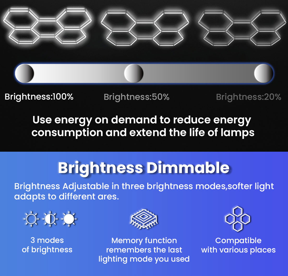
The technical reality is that most standard kits are not dimmable. The specific LED drivers used in these budget-friendly systems cannot handle variable voltage. Attempting to dim standard drivers causes severe flickering. It will also lead to premature driver failure and void your warranty.
If you require dimming capabilities, you must source specific dimmable drivers. Verify compatibility directly with the manufacturer before purchase. You must then match these drivers with compatible wall dimmers. Magnetic low-voltage or electronic low-voltage dimmers are often required. Mismatching dimmers and drivers guarantees poor performance. Always check the dimmer switch's minimum and maximum load ratings. LED loads behave differently than incandescent loads, and a standard rotary dimmer will not work.
Finished drywall ceilings require careful planning to conceal wires. Techniques include fishing wires through the ceiling cavity using fiberglass rods. You will need to install recessed junction boxes at the power injection points. If cutting drywall is not an option, use low-profile surface-mount raceways. Paint the raceways to match the ceiling color to minimize their visual impact. When drilling through top plates to drop wires down the wall, use a flexible drill bit and a bumper ball to avoid damaging existing drywall.
Open joists or unfinished ceilings offer easier access. Secure Romex or power cables along the sides of the joists using proper electrical staples. Maintain a safe distance from HVAC ductwork and hot water pipes. Keep wiring organized and running parallel or perpendicular to the joists for a professional appearance. Never drape wires diagonally across open joists. This is a code violation and looks terrible.
Drop ceilings provide an excellent opportunity to hide power supplies. Utilize the grid structure to conceal external transformers and excess cabling. You must ensure the weight of the lights and cables is properly supported. Do not rest heavy transformers directly on fragile acoustic ceiling tiles. Secure them to the structural ceiling above the drop grid using hanger wire and metal brackets.
The Y-cable strategy is vital for large grids. Manufacturers provide specialized power input cables to balance the electrical load. You must strategically place these cables across the grid. Do not feed power from just one corner of a massive setup. Distribute the power injection points evenly to prevent voltage drop.
Understand the difference between connector types. Differentiate between 2-pin and 3-pin grounded connectors. Grounded connectors are vastly superior for safety, especially in metal-framed structures. They provide a safe path for fault currents, protecting both the equipment and the user. If your kit uses 2-pin connectors, it relies entirely on double insulation for safety.
Avoid electrical bottlenecks by splitting a massive grid into smaller sub-grids. If a manufacturer states a maximum of 25 tubes per power lead, do not connect 30. Split the layout into two or three separate sections. Provide each section with its own dedicated power lead. This bypasses the maximum tube-per-connection limit and ensures uniform brightness.
| Grid Size | Recommended Power Injection Points | Wiring Strategy |
|---|---|---|
| Small (5-10 Hexagons) | 1 Point | Single feed at the corner or center. |
| Medium (11-25 Hexagons) | 2 Points | Split grid in half. Feed opposite ends. |
| Large (26+ Hexagons) | 3+ Points | Divide into distinct zones. Feed each zone independently. |
Overloading daisy-chained connectors is the most common failure point. Never exceed the manufacturer's stated limit for continuous connected tubes. This limit is often capped around 20 to 30 tubes per power lead. Pushing beyond this limit causes the plastic connectors to melt due to excessive heat buildup. Always verify the maximum run length in your specific manual. We have replaced countless melted Y-connectors because installers ignored the tube limit.
Series-like layouts create a single point of failure. If one connector fails at the start of a run, it kills power to the entire downstream grid. Mitigate this risk by utilizing multiple power injection points. Creating a closed-loop circuit where power feeds from two directions can also increase reliability. This ensures that a single loose connection does not darken half your garage.
Poor grounding and electrical surges destroy sensitive LED drivers. Ensure your garage subpanel has proper, verified grounding. Use surge-protected circuits for high-end lighting installations. Voltage spikes from the utility grid or heavy machinery can instantly fry the internal components of your lighting system. Whole-house or subpanel surge protectors are excellent investments. A Type 2 surge protective device installed at the breaker panel offers the best defense.
Non-compliant DIY wiring carries severe legal and financial risks. Outline the threshold where DIY ends and professional help begins. Assembling the plastic tubes is a DIY task. Hardwiring directly into a 200-amp breaker panel is not. Performing unlicensed electrical work without a permit violates local building codes. In the event of an electrical fire, unpermitted wiring will void your home insurance policy. Always pull the necessary permits and schedule inspections with your local building department.
When planning your layout, consider the specific type of fixtures you are installing. Whether you are working with hexagonal LED lights or standard shop lights, the electrical principles remain identical. The total wattage dictates the wire gauge, the breaker size, and the number of required circuits. Proper planning prevents costly rework and dangerous electrical faults.
A: It depends on the total wattage of the lights and the amperage of the circuit. A standard 15-amp, 120V circuit safely supports up to 1,440 continuous watts. You must calculate the combined wattage of all tubes. If your total exceeds 1,440 watts, you must split the load across multiple circuits or install a dedicated 20-amp or 240V breaker.
A: Small kits under 500 watts can typically share an existing garage circuit. However, large wall-to-wall installations require a dedicated breaker. This prevents the lights from tripping the circuit when heavy appliances like air compressors, table saws, or garage refrigerators cycle on and draw sudden spikes of power.
A: Yes, many kits include standard 120V plug-and-play power cords. This is safe as long as the total wattage of the lighting grid does not overload the outlet's circuit. You must ensure the outlet is properly grounded and not heavily loaded by other garage devices.
A: No. Manufacturers strictly limit how many tubes can be connected in a single continuous run. Exceeding this limit causes severe voltage drop, resulting in dim lights at the end of the chain. More importantly, it overloads the initial connectors, creating a severe fire hazard due to melting plastic.
A: For a seamless look, power cables must be routed through the ceiling cavity using fish tape. You install recessed junction boxes directly above the power injection points. If cutting drywall is impossible, use low-profile, paintable surface-mount raceways to conceal the wires as they run to the nearest wall outlet.
A: This is caused by voltage drop. When too many tubes are daisy-chained on a single power lead, electrical resistance reduces the voltage reaching the final tubes. To fix this, you must split the grid into smaller sections and provide additional, separate power injection points directly from the main power source.


